
Small eInkDisplay
written by Gohith Reddy on 10/17/2025
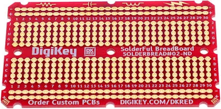
Last year at RowdyHacks 2024, MLH was giving away solderable breadboards and PCB rulers from digikey. Rather than just hoarding the breadboard pictured below, I decided to put it to good use by making something with it.
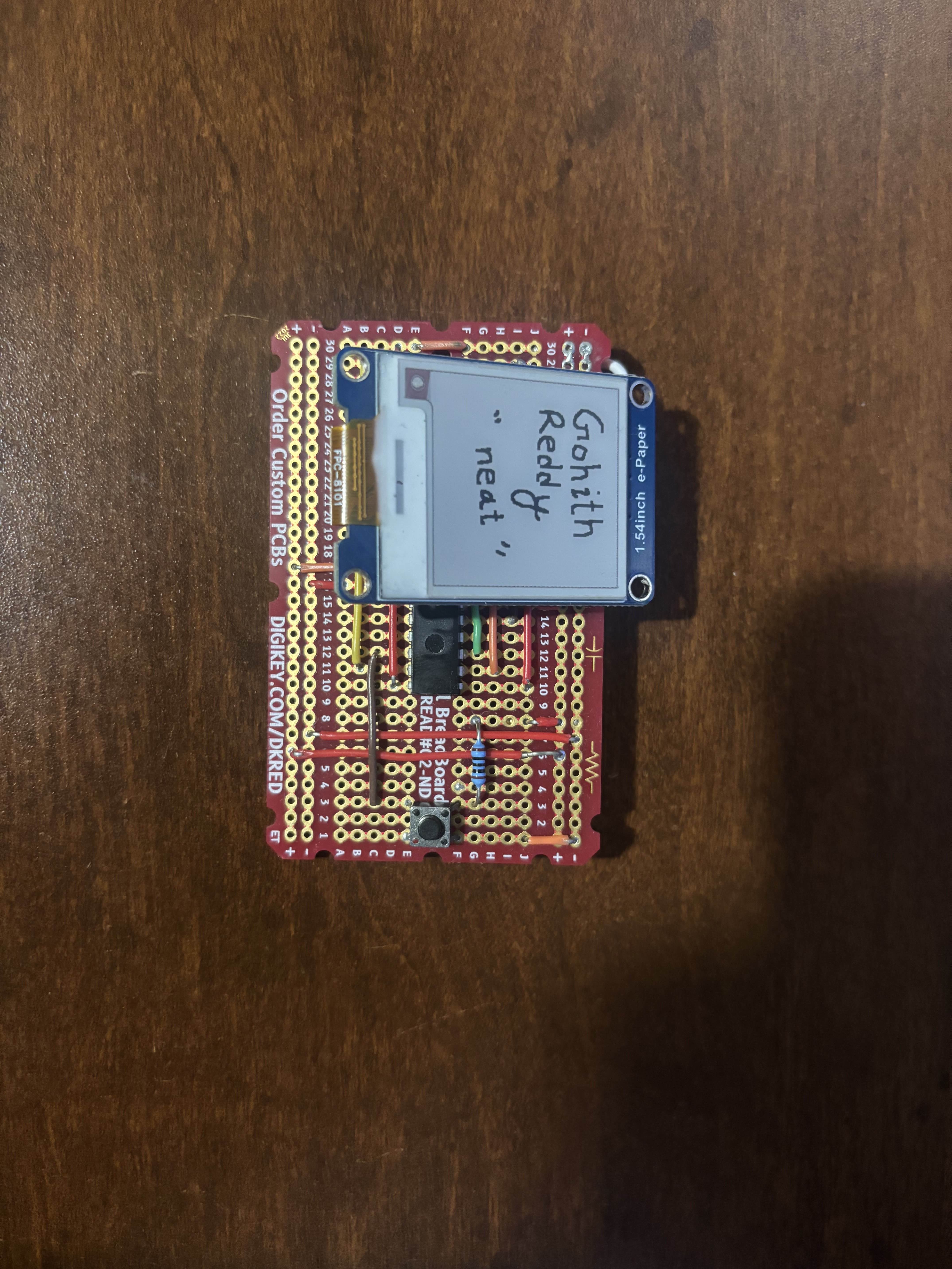
Since this board is roughly credit-card shaped, I thought it would be cool if I could make something from it that would display some information about me like a business card. Although I could've used a standard LCD display, I thought it would be really cool to use an eInk display so that the image would stay on the screen for a while. Since an Arduino already uses a microcontroller, I thought it would be really simple to just get the ATmega328p chip and program it. Boy was I wrong.
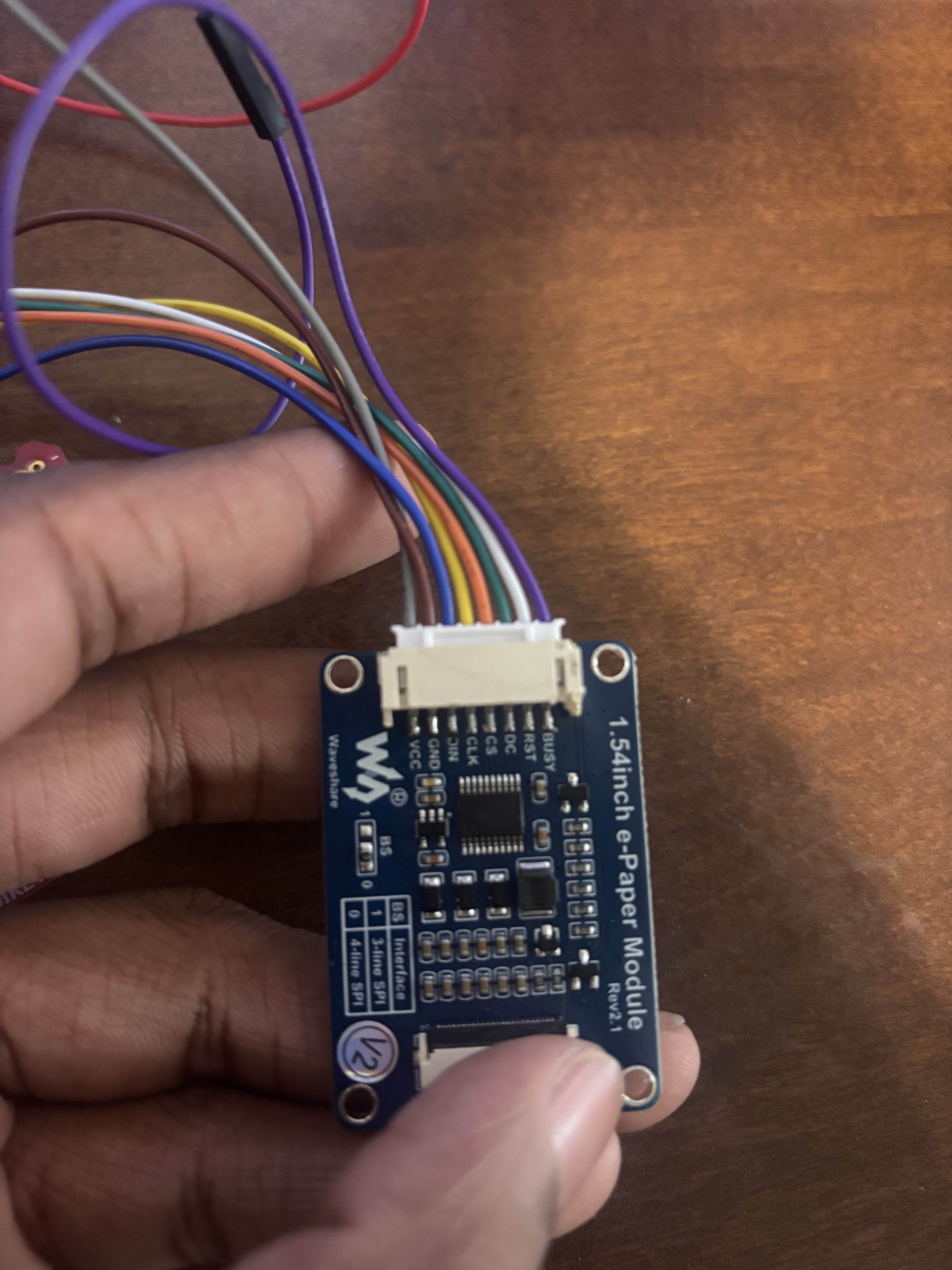
The display I chose, the 1.54inch e-Paper Module from Waveshare, already came with code to display some basic images on it. The only issue is that the images are displayed in lines of 8 pixels with a hex value describing which pixels are black and white. For reference, here is a part of the example image's code.
//within imagedata.cpp
#include "imagedata.h"
#include <avr/pgmspace.h>

const unsigned char IMAGE_DATA[] PROGMEM = {
0XFF,0XFF,0XFF,0XFF,0XFF,0XFF,0XFF,0XFF,0X8F,0XFF,0XFF,0XFF,0XFF,0XFF,0XFF,0XFF,
0XF1,0XFF,0XFF,0XFF,0XFF,0XFF,0XFF,0XFF,0XFF,0XFF,0XFF,0XFF,0XFF,0XFF,0XFF,0XFF,
0XFF,0X8F,0XFF,0XFF,0XFF,0XFF,0XFF,0XFF,0XFF,0XF1,0XFF,0XFF,0XFF,0XFF,0XFF,0XFF,
...
0XFF,
};
Of course most images aren't saved in this format, so I'd have to process my own images before I upload them to the screen. I chose to draw some 200x200 images in black and white so that it would be very easy to convert it to hex. I just wrote a basic script for it. It outputs the values to stdout so that I can copy paste it directly into the arduino code. This just makes it so that I don't have to deal with the text around it, but of course I would've implemented it differently for a complete pipeline
//epaper_pic_to_paper.py
from PIL import Image
import sys

def image_to_bytes(image_path):
    # Load and convert to 1-bit B/W
    img = Image.open(image_path).convert("1")
    img = img.resize((200, 200))  # Ensure size is 200x200

    pixels = img.load()
    width, height = img.size

    byte_rows = []

    for y in range(height):
        row_bytes = []
        for x in range(0, width, 8):
            byte = 0
            for i in range(8):
                if x + i < width:
                    bit = 1 if pixels[x + i, y] == 255 else 0
                    byte = (byte << 1) | bit
            row_bytes.append(byte)
        byte_rows.append(row_bytes)

    return byte_rows


data = image_to_bytes(sys.argv[1]) #or change this to filename

for row in data:
    print(", ".join(f"0x{byte:02X}" for byte in row))
    print(",")
Pretty basic script, but it works for my needs to implement my own images into the e-ink. All of these worked on my Arduino, but getting these to work on an ATmega328p was so much harder.

It was so incredibly hard to actually upload everything. I planned on using my Arduino R3's microcontroller seat to burn the code into the controller and then have it run on the breadboard, but the ATmega needs is a 16MHz crystal oscillator and some capacitors to actually run to code anyway, at least without burning the bootloader. I eventually figured out that I had to use an In-Circuit Serial Programmer (ICSP) to program everything. This tool is essentially an external way to program chips, like how the Arduino IDE uploads code over the USB port. This would've cost me about $12 to buy one, but I didn't want to spend the money on it. Since I didn't have one, I wanted to try to program the UNO R3 to become one. I tried to use the UNO's built in "use the arduino as as ISP" feature and the SPI pins on the ATmega to burn the bootloader / upload the code onto the ATmega328p, but it just resulted in a bunch of errors.

After a while of trying, I eventually stopped getting the expected errors and thought that I bricked all of my ATmegas. I somehow eventually just "unbricked" them after a while. Eventually, I realized that the ATmegas I bought had already been pre made to run at 16MHz, so I couldn't reprogram the chips without a crystal oscillator. I realized that I could actually put the chips into the UNO's chip seat and then use an external ICSP to upload the code and burn the bootloader. Still not wanting to pay $12 for what would've saved me hours of work, I used a pi pico I had lying around as an ICSP, and it worked! I successfully got the chips working after a long while! This is a picture of the pi programming the arduino to program the ATmega328p.

Now, the next step was to solder everything together. This wasn't the hardest step besides just being a little time consuming. One issue I did come into was how the display actually connected to its pcb. The connector was mostly plastic with multiple pins blocking the SMD pads, plus it was really just in the way of making the device as thin as possible. I pretty much just took off as much solder as I could from the supporting pads on the sides, then covered the SMD pins with solder so I could heat them all up simultaneously.
The next issue I faced was actually soldering to these pads. I had some wires lying around, but the problem was the wire inside was actually many small intertwined copper wires inside. This made soldering to the pads with strength or without short circuiting almost impossible for a beginner solderer like me. I ended up buying some solid 22-guage wire, roughly the size of the wires used for breadboards, and soldered those to the pads. Still took me longer than I'd like to admit but I eventually found that putting solder on the pads first and then putting the wire in was a whole lot easier than putting solder on the wire-tip and hoping the solder sticks to the pad. Here's the finished solder joints.

Not the prettiest joint, I must admit, but they work! I made sure to test each pin for shorts before plugging them in... aaand it worked! I tried finding a thin battery that could do the job, so I tried 2x CR2032s, but they weren't able to handle the current. I tried a couple different batteries but the display has a very tight 3.3V or 5V requirement and wont turn on without that, so unfortunately it can only change displays with an external power source. Here's the final side shot and it switching between two custom images I made!
